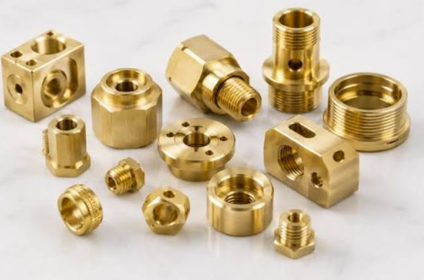
Brass is widely considered one of the easier engineering metals to machine. It can support high cutting speeds, clean dimensional features, and efficient production of fittings, connectors, valves, bushings, and electrical components. However, good machinability does not automatically produce a reliable assembled part. Problems often appear where threads, sealing faces, precision bores, cross-holes, and press-fit diameters interact within a compact component. A part may pass a basic dimensional inspection yet leak, loosen, deform, or resist assembly. Reliable brass CNC machining therefore requires more than selecting suitable cutting data. The material grade, functional tolerance, feature relationship, deburring method, plating thickness, and inspection plan must all reflect how the finished component will be installed and used.
Why Easily Machined Brass Parts Can Still Fail During Assembly
The reputation of brass as a free-machining material can create unrealistic expectations. A drawing may contain dozens of individually achievable dimensions, but the functional result depends on how those dimensions interact.
For example, an internal thread may pass a plug gauge while remaining slightly misaligned with the bore it is supposed to seal. A press-fit diameter may meet its size tolerance before plating but become too large after nickel deposition. A cone seat may have an acceptable average roughness while a single circumferential tool mark creates a leak path.
Common assembly problems in CNC machined brass parts include:
- Incomplete thread starts that catch or cross-thread during installation
- Thin walls that distort under tightening or pressing loads
- Burrs remaining where cross-holes intersect internal passages
- Scratches across gasket faces or metal-to-metal sealing seats
- Plating buildup that reduces thread clearance or bore diameter
- Misalignment between threads, bores, valve seats, and external datums
- Excessive edge breaking that reduces the effective sealing area
These failures are rarely caused by brass alone. They usually result from treating related features as independent dimensions rather than as one functional interface.
See also: Revolutionising Medical Diagnostics with Advanced Imaging Technology
Brass Alloy Selection Changes Cutting Behavior and Part Performance
“Brass” describes a family of copper-zinc alloys rather than a single material. Alloy composition affects chip formation, tool life, surface integrity, forming behavior, corrosion performance, regulatory suitability, and material cost. The selected grade should therefore appear clearly on the drawing and purchase specification.
C360 Brass Supports Efficient Turning and Thread Production
C360 free-machining brass is frequently selected for turned fittings, inserts, terminals, valve parts, threaded bodies, and other high-volume components. It generally produces manageable chips and permits efficient cutting of detailed features.
Its machinability supports operations such as:
- External and internal threading
- Knurling and grooving
- Precision drilling and boring
- Cross-hole production
- Form turning
- Parting and backworking
Nevertheless, a machinable alloy does not eliminate engineering control. Long, slender parts can still experience runout. Thin sections can deform under collet pressure. Poorly positioned cross-holes can leave difficult internal burrs. Tool condition also affects thread form and sealing-seat quality.
For a broader discussion of grades, tooling, dimensional control, and finishing options, this brass CNC machining guide provides further engineering information.
Lead-Free Brass Requires Different Machining Expectations
Lead-free grades may be required for potable-water components, regulated applications, or customer-specific environmental standards. These materials should not automatically inherit the same cutting assumptions used for C360.
Depending on the alloy, lead-free brass machining may involve different chip behavior, cutting forces, tool wear, or surface-finish results. Production planning should establish:
- The exact alloy designation and governing material standard
- Whether material substitution is permitted
- Required certificates or regulatory documentation
- Whether samples and production parts will use the same grade
- Which functional surfaces need additional finish control
The phrase “lead-free brass” is not sufficiently precise for manufacturing. Two nominally lead-free materials may behave differently during turning, drilling, threading, or deburring. Clear alloy identification prevents quotation assumptions from becoming production problems.
Brass Threads Need More Than a Passing Thread Gauge
Threads are often treated as complete once they pass the applicable GO and NO-GO gauges. Gauging is essential, but it cannot verify every condition that influences installation, sealing, or alignment.
Thread Starts, Runout, and Burrs Affect Real Assembly
A threaded feature must guide the mating component smoothly into full engagement. The start should be complete and properly chamfered without removing unnecessary thread length. An excessive entrance chamfer can shorten engagement, while a sharp or incomplete first thread can damage the mating part.
Thread runout also requires enough space. If the thread ends directly against a shoulder, an unsuitable relief may prevent the mating component from seating completely. This can be mistaken for an incorrect thread even when the pitch diameter is acceptable.
For brass threaded parts containing cross-holes, burr control becomes especially important. A drilling operation that breaks into a threaded bore may push a small burr into the thread root. The thread gauge may displace or miss it, while the actual mating fastener catches during installation.
Functional thread review should consider:
- Pitch and thread form
- Effective engagement length
- Entrance chamfer
- Thread relief
- Relationship to the sealing surface
- Burrs at intersecting holes
- Concentricity with the mating bore
Tightening Torque Can Distort Thin Brass Features
Brass bodies are frequently lighter and thinner than comparable steel components. Tightening loads can deform a thin threaded wall, an unsupported hexagonal section, or a narrow port connection.
This is particularly important when a component is tightened using a wrench applied far from the supported area. The thread may remain intact while the surrounding bore becomes oval or the sealing face tilts. Assembly torque should therefore be considered during part design rather than left entirely to the final installer.
Prototype evaluation can include representative mating hardware and realistic torque conditions. This provides more useful evidence than checking the thread in an unloaded state alone.
Brass Sealing Surfaces Require Geometry and Finish Control
A sealing interface usually depends on several connected characteristics. Surface finish matters, but finish alone cannot compensate for incorrect geometry, misalignment, inadequate contact width, or physical damage.
The following requirements vary according to the sealing method:
- Sealing interface: O-ring groove
- Primary controls: Groove width, depth, edge condition and surface finish
- Frequent source of failure: Sharp edges, burrs or incorrect compression
- Sealing interface: Metal cone seat
- Primary controls: Angle, concentricity, contact band and tool marks
- Frequent source of failure: Interrupted contact or circular scratches
- Sealing interface: Flat gasket face
- Primary controls: Flatness, finish and available sealing width
- Frequent source of failure: Clamp marks or damaged edges
- Sealing interface: Thread seal
- Primary controls: Thread form, engagement and approved sealing method
- Frequent source of failure: Incomplete threads or contaminated surfaces
A cone seat should be concentric with the flow bore and mating thread. If these features are produced from different setups without suitable datum control, each may pass an individual size check while failing to align during assembly.
O-ring grooves present a different challenge. Their edges must permit installation without cutting the elastomer, but excessive rounding can change the available sealing geometry. Tool marks, chips, and embedded debris must also be removed before final inspection.
Surface Specifications Must Match the Seal Type
There is no universal surface-roughness value suitable for every brass sealing feature. The appropriate requirement depends on the seal material, contact pressure, fluid, operating temperature, and sealing geometry.
More restrictive surface-finish requirements should be applied only where they support function. Specifying an exceptionally fine finish across an entire component may add machining time without improving performance. A better drawing identifies the actual sealing region and states the required condition there.
Handling is equally important. A correctly machined seat can be damaged during deburring, washing, bulk transport, plating, or final packaging. Soft separators, capped ports, or dedicated trays may be justified when a small surface defect could cause leakage.
Press Fits Become Unstable When Brass Walls Are Too Thin
A brass press fit tolerance cannot be selected from nominal diameter alone. The surrounding wall thickness, component length, mating material, surface condition, insertion method, and operating temperature all affect the result.
Too little interference may allow movement under vibration or thermal cycling. Excessive interference can split the brass body, distort an adjacent bore, or produce insertion forces that damage the mating component.
Design review should consider four related factors:
- The minimum and maximum interference resulting from both part tolerances
- The radial wall thickness surrounding the fitted feature
- The entrance chamfer and alignment during pressing
- Whether plating or another coating changes the final diameter
Thin sleeves and bushings may also become slightly out-of-round after removal from the machine. Measuring only one diameter orientation can conceal this condition. Roundness and cylindricity may be more relevant than a simple two-point diameter check when the part supports a bearing, pin, or precision insert.
Press-fit validation should use representative mating parts. A calculation establishes the starting range, while controlled assembly testing confirms insertion force, retention, deformation, and post-assembly dimensions.
Hidden Burrs in Cross-Holes Can Damage Threads and Seals
Internal burrs are among the most easily overlooked risks in brass fittings machining. Compact fittings, valve bodies, manifolds, and connector parts often contain intersecting holes that cannot be inspected directly with the unaided eye.
A drill breaking into a larger passage may leave a feathered edge or folded burr. That material can detach during service, restrict flow, interfere with a valve, damage a seal, or enter another system component.
Effective brass burr removal must be strong enough to remove loose material without changing a calibrated opening or sealing edge. Possible methods include controlled mechanical tools, brushing, abrasive-flow techniques, thermal processes where appropriate, or carefully developed manual operations. The correct method depends on the geometry and cleanliness requirement.
Inspection should focus on the actual intersection, not merely the external hole entrance. Borescopes, magnification, air-flow verification, flushing, or part-specific visual standards may be required for critical internal passages.
Projects combining threaded fittings, internal flow paths, sealing features, and secondary finishing benefit from integrated brass CNC machining services that consider machining, deburring, cleaning, and inspection as a connected production system.
Plating Thickness Must Be Included in the Tolerance Strategy
Brass parts may receive nickel, tin, chrome, silver, or other finishes for appearance, corrosion resistance, solderability, conductivity, or wear performance. These coatings alter dimensions and sometimes affect electrical or sealing behavior.
Before production begins, the drawing should establish whether dimensional requirements apply before or after finishing. This is especially important for:
- Precision bores
- External press-fit diameters
- Internal and external threads
- O-ring grooves
- Electrical contact areas
- Metal sealing surfaces
Before plating, the machining allowance must reflect the expected coating buildup. Blind holes and recessed features may receive a different thickness from exposed external surfaces, so subtracting a single nominal coating value from every dimension is not always reliable.
After plating, critical dimensions should be verified in their finished condition. Threads may require masking or post-plating verification. Electrical contacts may need a specific coating system, while sealing areas may require protection from nodules, rack marks, or uneven deposition.
Clear drawing notes should also define whether bare areas are intentional. Otherwise, the plater and machine shop may make different assumptions about threads, grounding points, or surfaces that contact elastomeric seals.
Inspection Should Reproduce Functional Conditions
Inspection is most effective when it reflects how a component works. A universal measurement routine may confirm drawing dimensions without detecting the condition most likely to cause field failure.
For a threaded and sealed brass component, a suitable inspection plan may combine:
- GO and NO-GO gauges for thread acceptance
- Optical or magnified inspection of thread starts
- Positional or concentricity checks between related features
- Surface inspection of sealing regions
- Diameter and roundness measurement for press fits
- Internal examination of cross-hole intersections
- Leak or pressure testing where specified
- Cleanliness verification for controlled fluid systems
A leak test must also represent the intended requirement. Test pressure, medium, stabilization time, allowable leakage, fixture design, and temperature can affect the result. These conditions should be agreed rather than assumed.
Likewise, inspection of a plated component must distinguish between machining variation and coating variation. When finished dimensions are critical, measuring only the pre-plated parts leaves a significant gap in verification.
Stable Brass Production Requires Control Beyond the First Sample
A successful first article proves that one set of parts can meet the requirement. It does not by itself guarantee consistency across repeated production batches.
During volume production, thread dimensions may drift as tools wear. Drill condition can change burr formation at intersecting holes. Collet pressure may affect thin-wall geometry. Variations in bar stock can influence cutting response, while changes in plating thickness may alter fits.
A practical control plan should identify which characteristics need periodic verification and which events require renewed first-piece approval. Such events might include a tool change, material-lot change, machine restart, fixture replacement, program revision, or transition to a new finishing batch.
Packaging also belongs in the quality plan. Bulk packing may be acceptable for robust fittings, but exposed sealing seats and cosmetic plated faces can rub against each other during transport. Protection should correspond to the sensitivity and value of the functional surfaces.
Buyers sourcing parts that combine turning, milling, drilling, threading, and secondary operations can review Yueyi Precision’s broader custom CNC machining capabilities when assessing whether a supplier can coordinate the complete manufacturing requirement.
Reliable Brass Components Begin with the Functional Interface
The main advantage of brass is not that every brass component is automatically simple. Its value lies in combining machinability, useful mechanical properties, corrosion resistance, conductivity, and suitability for detailed functional parts. Realizing those advantages requires the manufacturing plan to reflect the finished assembly.
Threads must be evaluated together with their leads, reliefs, mating bores, and tightening loads. Sealing surfaces require both suitable geometry and controlled handling. Press fits must account for wall strength, coating buildup, and assembly force. Internal burrs and contamination must be addressed before they reach the customer’s system.
When requesting a quotation for precision brass components, buyers should provide the specified alloy, finished condition, mating relationships, functional tolerances, critical surfaces, testing requirements, and expected production quantity. This information allows the manufacturer to select an appropriate machining, deburring, finishing, and inspection strategy.
Yueyi Precision supports drawing-based production of custom brass parts involving turned features, milled details, precision threads, internal passages, sealing interfaces, and secondary finishing. Early technical review can identify risks before tooling and batch production begin, helping engineers obtain parts that not only meet the drawing but also assemble and perform as intended.