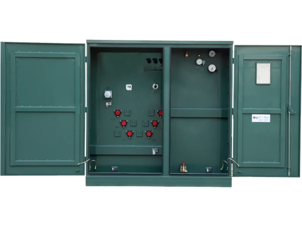
A zigzag transformer is a specialized transformer used primarily in three-phase electrical systems to provide a neutral point, support grounding arrangements, and help manage certain zero-sequence currents. Unlike a conventional transformer designed mainly for changing voltage, a zigzag transformer is often installed as part of a grounding or system-protection strategy.
Its winding arrangement gives the transformer its distinctive name and allows it to perform functions that standard transformer configurations may not provide as effectively.
What Is a Zigzag Transformer?
A zigzag transformer, also called a zig-zag grounding transformer, is a three-phase transformer with specially interconnected windings. Each phase winding is divided into sections, with the sections connected in a way that creates the characteristic zigzag arrangement.
One common purpose is to establish an artificial neutral point on a three-phase system that does not otherwise have a neutral connection.
This neutral point can then be connected to ground directly or through an impedance, depending on the grounding design.
Why Is a Zigzag Transformer Used?
Many three-phase electrical systems need a defined grounding reference even though the source itself may not provide a neutral.
A zigzag transformer can provide that neutral reference without necessarily supplying a conventional secondary voltage for loads.
This makes it useful in systems where grounding and fault-current management are the primary objectives.
Typical applications include:
- Industrial power systems
- Utility substations
- Renewable energy installations
- Generator systems
- Medium-voltage distribution networks
- Motor systems
- Transformer substations
- Electrical systems requiring a grounding neutral
The exact application depends on the electrical system and grounding requirements.
How the Zigzag Connection Works
The winding arrangement is the main feature that distinguishes this transformer from conventional designs.
The winding sections are connected so that the magnetic effects of balanced three-phase currents largely cancel within the transformer. Under normal balanced conditions, relatively little current flows through the grounding connection.
During a ground fault, however, zero-sequence current can flow through the transformer and grounding path.
This characteristic allows engineers to establish a controlled path for ground-fault current.
Grounding Transformer Applications
One of the most common uses of a zigzag transformer is grounding an otherwise ungrounded or inadequately grounded three-phase system.
The transformer creates a neutral point that can be connected to ground through a grounding resistor or reactor.
This arrangement allows the engineer to control the magnitude of ground-fault current.
The grounding method is selected according to the system voltage, fault-current requirements, protection scheme, and applicable electrical standards.
Neutral Formation
A zigzag transformer can create a neutral point without requiring a conventional neutral conductor from the upstream source.
This can be useful for systems where the three-phase source only provides three phase conductors.
Once the artificial neutral is established, it can serve as the reference point for grounding equipment and system protection.
The neutral point should be designed according to the complete electrical system rather than treated as a standalone transformer feature.
Ground-Fault Current
Ground faults can produce dangerous currents that need to be detected and cleared by protective equipment.
A zigzag transformer provides a path for zero-sequence current during a ground fault. The resulting current allows protective relays and other devices to detect the fault and initiate circuit interruption.
The grounding transformer therefore works together with protection equipment rather than replacing circuit breakers or protective relays.
Grounding Resistors and Reactors
A zigzag transformer can be combined with a grounding resistor or reactor to control fault current.
A resistor limits the amount of current that can flow during a ground fault while providing a measurable current for protective devices.
A reactor uses inductive impedance to limit fault current.
The appropriate configuration depends on the desired grounding method and the requirements of the electrical network.
Zigzag Transformer vs. Conventional Transformer
A conventional transformer is generally designed to transfer electrical energy between circuits while changing voltage.
A zigzag transformer used for grounding has a different primary purpose. It may not provide a conventional load-serving secondary output.
Its design focuses on establishing a neutral point and providing a path for zero-sequence currents.
This distinction is important when specifying equipment because the kVA rating and electrical configuration must reflect the intended application.
Zero-Sequence Current
Zero-sequence current is an important concept in grounding-transformer applications.
During balanced three-phase operation, the three phase currents are normally displaced by 120 electrical degrees and their vector sum is approximately zero.
During certain ground faults, the current distribution changes. Zero-sequence current can then flow through the grounding system.
The zigzag transformer’s winding arrangement provides a suitable path for this current while maintaining the desired behavior during normal balanced operation.
Protection Coordination
A grounding transformer should be coordinated with the protection system.
Engineers may evaluate the transformer characteristics, grounding impedance, fault-current levels, relay settings, breaker ratings, and system grounding method together.
Incorrect coordination can result in insufficient fault current for reliable detection or excessive current that places unnecessary stress on electrical equipment.
Protection studies can help establish suitable settings before the system is commissioned.
Applications in Renewable Energy
Renewable energy installations can use grounding transformers where the electrical architecture requires a neutral grounding point.
Solar power plants, wind projects, battery systems, and other power-conversion installations may have three-phase systems without a conventional neutral connection.
A zigzag transformer can provide the required grounding reference, depending on the inverter and system design.
The transformer must be selected according to the voltage, grounding method, fault duration, and other characteristics of the renewable energy system.
Sizing a Zigzag Transformer
Sizing is different from selecting a conventional load-serving transformer.
The required rating depends on the grounding duty, expected fault current, fault duration, system voltage, grounding impedance, and applicable design requirements.
Engineers should establish the maximum ground-fault current and duration before specifying the transformer.
The transformer may need to withstand a specified fault current for a particular period without exceeding its thermal or mechanical limits.
Installation Considerations
A zigzag transformer should be installed according to the manufacturer’s instructions and the approved electrical design.
Installation planning may involve:
- Foundation or mounting arrangement
- Grounding connections
- Neutral connection
- Grounding resistor or reactor
- Cable routing
- Electrical clearances
- Protective devices
- Enclosure requirements
- Environmental conditions
- Maintenance access
Outdoor installations may require weather-resistant enclosures and suitable environmental protection.
Maintenance Requirements
Maintenance requirements depend on the transformer construction and installation environment.
Inspection may include checking electrical connections, grounding conductors, insulation, enclosure condition, temperature, and signs of overheating or physical damage.
If the transformer is combined with a grounding resistor or reactor, those components should also be inspected and tested according to the manufacturer’s recommendations.
Regular testing of the grounding and protection system can help confirm that the equipment remains capable of responding correctly to ground faults.
See also: Effective Online Payment Solutions for Modern Businesses
Selecting a Zigzag Transformer
Before specifying a zigzag transformer, the electrical design should establish:
- System voltage
- Frequency
- Grounding method
- Maximum ground-fault current
- Fault duration
- Neutral grounding arrangement
- Grounding resistance or reactance
- Protection requirements
- Installation environment
- Applicable electrical standards
Providing this information to the transformer manufacturer allows the equipment to be designed for the actual grounding duty.
Final Considerations
A zigzag transformer is a specialized component that can provide an artificial neutral and controlled path for zero-sequence current in three-phase electrical systems. It is particularly useful where a system requires grounding but does not have a conventional neutral connection.
Proper selection requires an understanding of system voltage, grounding philosophy, fault-current requirements, protection coordination, and installation conditions. Because grounding equipment directly affects electrical safety and fault protection, the design and installation should be completed by qualified electrical professionals using applicable standards and manufacturer specifications.